The following challenge was presented as part of the Capstone Design Project for a course in Digital Logic Design: assume that a company selling gasoline would like to prevent customers from excessively ‘topping-off’ their gas tanks, thus risking a fire hazard from overflowing and spilled gasoline. To minimize this problem, their pumps currently turn off when the back pressure from the gas tank gets too large while the pump nozzle is activated (i.e., the pump will shut off when the tank is nearly full), but they would now like their pumps to shut down permanently if a customer attempts to pump again after this initial shut off, with a manual reset by gas station personnel required.
The secret to solving such a problem is by designing a finite-state machine (FSM). A state machine is a computational mathematical model frequently used in the design of computer programs and circuits using sequential logic. Because a series of steps are required to carry out the desired outcome, the machine resides in one state at a time; i.e., its current state. A triggering event or condition then causes it to change from its current state to the next state; i.e., a transition. Many modern devices perform predetermined actions depending on a sequence of events, such as vending machines which dispense products when a certain amount of money is inserted, elevators, traffic signals, combination locks, security systems and, in this case, gas pump controllers.
When designing a FSM, first, the various states are defined, with binary values arbitrarily assigned to them. Next, a state transition diagram and state transition table are created. From these, Karnaugh maps are generated and the particular logic functions needed for the circuit derived from them. Finally, the circuit design is created, having been derived from the logic provided in the previous steps–first, in simulation, and then ultimately built and tested using actual hardware. There are two primary types of FSMs: the so-called Mealy FSM and the Moore FSM. The design styles of both have relatives pros and cons. Because of this, both Mealy and Moore-style designs are developed, tested and evaluated, with a choice made on which one ultimately provides the best design for the project. Influential factors include: which design uses the fewest amount of parts, least amount of wiring, least amount of complexity, and least amount of cost [1].
As mentioned, Moore and Mealy machines have pros and cons associated with each: the output of Moore machines depends only on states, while Mealy machine outputs depend on both inputs as well as states. Thus, a Mealy machine can usually be designed with fewer states, which makes it simpler and more efficient. On the other hand, a Mealy machine is not inherently synchronous, while the Moore machine is. The synchronous operation of circuits is obviously critical when states, transitions, and triggering events are time-dependent. The fact that a Moore machine offers this benefit inherently without the need for additional logic gates and wiring, unlike the Mealy machine, makes it attractive, as well.
Thus, the dilemma: which is better? Moore or Mealy? In the creation of this design project, the question was considered in an attempt to arrive at the best of both worlds: i.e., the simplicity of a Mealy machine yet with the built-in synchronicity of a Moore machine. While a Mealy machine can certainly be made synchronous, as mentioned, it requires additional logic and hardware, thus eliminating the “simplicity factor” that makes it so elegant. Thus, if it were possible to design a Moore machine that could operate fully on a limited number of states and still fulfill the desired output (i.e., achieve simplicity), while still maintaining synchronicity, the best of both worlds could be achieved in a single FSM model.
Step One: State Definitions
The first goal was to create a simple, four-state definition table that could be used by either a Mealy or Moore machine, as defined below:
Table 1: State Definition Table
| State | Definition | Binary values |
| S0 | Reset/Initialize | 00 |
| S1 | Nozzle On-Pressure Low; gas will pump; temporary shut down without lockout possible. | 01 |
| S2 | Nozzle On-Pressure High; automatic shut off. Pump reset is possible for next customer. | 10 |
| S3 | Second attempt to pump with Pressure High; permanent shut down (lockout) engaged, requiring employee reset. | 11 |
Next Steps: Create State Diagrams, State Transition Tables, and Karnaugh Maps
Next, the digital logic for both Mealy and Moore machine designs was derived by generating state diagrams, transition tables and Karnaugh (“K) Maps from the above state definition table. As hoped, it was found that an effective state transition table and K-Map could indeed be derived for the Moore machine as well as the Mealy machine.
Final Steps: Designing and Testing the Mealy and Moore Digital Circuits
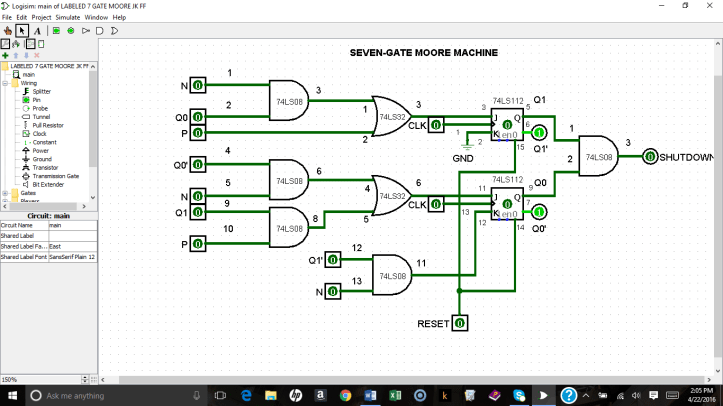
Once the digital logic for both Moore and Mealy designs was determined, the circuits were designed and tested using Logisim simulation software [2]. Because it required additional logic to provide synchronistic functioning, the Mealy design needed twelve logic gates in all to perform the operation. The Moore design, by contrast, required only seven. (Wiring and hardware specifications are also provided on the Moore design, given below.)
Figure 1: 12-Gate Synchronous Mealy Design using Logisim Software
.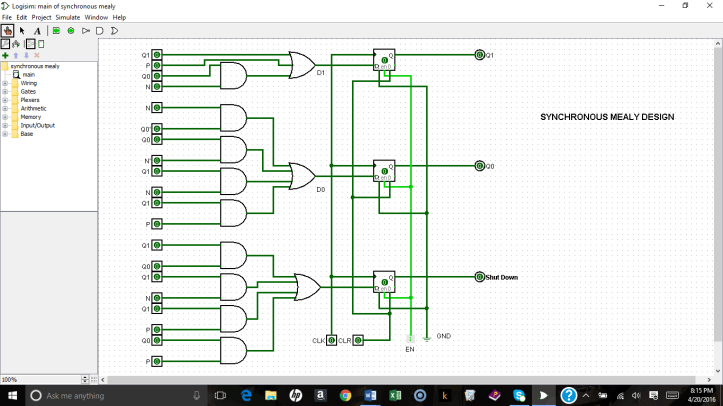
Figure 2: 7-Gate Moore Machine
Last Step: Design Analysis and Selection
Table 2 below uses the Kepner Tregoe (KT) Decision Analysis method [3] and provides a weighted score for each of the following criteria:
Weight
- 50%: Number of gates/ICs used.
- 30%: Number of inputs in combinational logic.
- 20%: Number of different types of gates/flipflops and states.
Table 2: Design Selection Comparison Table
| Mealy | Weighted Score | Moore | Weighted Score | |
| Number of gates used | 12 | 6 | 7 | 3.5 |
| Number of inputs in combinational logic | 20 | 6 | 9 | 2.7 |
| Number of flip flops used | 5 | 4 | ||
| Number of states used | 4 | 1.8 | 4 | 1.6 |
| Total
(Lower Score is Better) |
13.8 | 7.8 |
Based upon the KT Decision Analysis method, the table above indicates that the Moore machine design was the simpler and better choice based on the following: it has fewer gates which, in turn, require fewer integrated circuits. Fewer ICs translate into less money spent and less space needed, both of great importance in engineering. Finally, it has fewer inputs in combinational logic which make wiring easier, with less chance for error. Utilizing only seven gates and four ICs, the design appears to be quite efficient.
This result likely flies in the face of what is expected, since Mealy machines are typically easier to design than similar Moore machines. In fact, it is generally the Mealy machine that requires less hardware. Had a 5-state Moore machine been chosen instead, the likely result would have been that the 4-state Mealy would indeed have been the better option. However, for reasons stated above, it seemed possible to build a functional Moore machine with only 4 states. In that case, the Moore machine clearly won out over the Mealy. Finally, as discussed, Moore machines have the additional benefit that they are automatically synchronous, since current outputs are always stable. A Mealy machine would require additional hardware to force it into synchronicity, making it harder to engineer.
Based on the criteria and weighting system, the Moore Machine turned out to be the better system for this problem.
Conclusion: Building the Design in Hardware
As a final step, the Moore machine was built in hardware, using a limited number of integrated circuits that were provided for the project. In all, only two 74LS08 ICs, one 74LS32 IC and one 74LS112 IC were needed for this design. Thus, this design provided a simple, low-cost solution for a digital controller that can easily be placed in all of the client’s gas pumps.

References:
[1] Marcovitz, Alan B., “Introduction to Logic Design” (3rd Ed.), McGraw-Hill, New York, NY (2010).
[2] Logisim Simulation Software, http://www.cburch.com/logisim.
[3] http://www.kepner-tregoe.com.
