For this project, I will show how to design a synchronous counter which is capable of storing data and counting either up or down, based on input, using either D flip-flops or J-K flip-flops. Specifically, the counter will count up: 0, 1, 2, 3, 0, 1, 2, 3, … when the input x = 1, and count down when the input x = 0.
Suggested state definition tables, transition diagrams, transition tables, K-maps for the respective logic functions, and schematics of the implementation using flipflops and logic gates for both a D flip-flop and a J-K flip-flop scenario will be given.
Brief Background
A flip-flop (also called a latch), is a circuit that has two stable states and is often used to store state information (e.g., on/off, 1/0, etc.). Indeed, it is a basic storage element used in sequential logic and a fundamental unit of digital electronic design for computer and communication systems, among others. Since it is a bistable multivibrator, the flip-flop circuit can change states when a signal is applied to one or more control inputs, conveniently resulting in one or two outputs. The flip-flop stores a single bit of data, and its two possible resulting states represent either a “one” or a “zero” condition. When used in finite-state machine design, the output and next state depend on both the current input as well as the current state, with the current state resulting from previous inputs. As a result, the flip-flop can be used to count pulses and synchronize variably-timed input signals with a basic reference signal [1]. While the terms flip-flop and latch are sometimes used interchangeably, we generally refer to the unit as a flip-flop if it is clocked; if it is simple (i.e., transparent or opaque), we refer to it as a latch [2].
The popular D (“data” or “delay”) flip-flop can really be thought of as a memory cell, a delay line, or a zero-order hold [3]. Its true usefulness is its ability to capture the value of the D-input at a defined moment or portion of the clock cycle (such as the rising edge). This value, in turn, becomes the Q output [4]. Inputs and resulting outputs can then be tracked and assessed by means of a truth table.
The J-K flip-flop, meanwhile, features two inputs: the so-called “J” input and the “K” input, named after the circuit’s inventor, Jack Kilby, along with four input combinations: logic “1,” logic “0,” “no change” and “toggle.” If both J and K inputs equal logic “1,” the J-K flip flop will toggle. A major benefit of the J-K flip-flop is that only one of its two input terminals–either SET or RESET–can be active at any one time, thus eliminating the possibility of an “invalid condition.” Likewise, if both J and K inputs are at logic “1” simultaneously, along with a clock input pulsed HIGH, the circuit will toggle from the SET to RESET state, or RESET to SET, as needed. When both terminals are HIGH, the J-K flip-flop behaves like a T-type toggle flip-flop [5].
As you can see, both flip-flops have their advantages. That said, we will show below how to design the synchronous counter using either of them.
DESIGN #1 – Synchronous Counter: D Flip-Flops
| State | Definition | Binary values |
| S0 | Reset/Initialize, no sequence | 00 |
| S1 | Count 1 | 01 |
| S2 | Count 2 | 10 |
| S3 | Count 3 | 11 |
Figure 1: State Transition Diagram (D Flip-Flops)
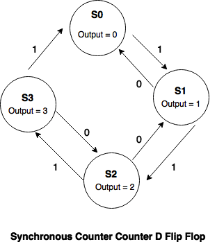
Table 2: State Transition Table (D Flip-Flops)
| Input | Present State | Next State | FF Inputs | |||||
| x | State | Q1 | Q0 | State | Q1+ | Q0+ | D1 | D0 |
| 0 | S0 | 0 | 0 | S3 | 1 | 1 | 1 | 1 |
| 0 | S1 | 0 | 1 | S0 | 0 | 0 | 0 | 0 |
| 0 | S2 | 1 | 0 | S1 | 0 | 1 | 0 | 1 |
| 0 | S3 | 1 | 1 | S2 | 1 | 0 | 1 | 0 |
| 1 | S0 | 0 | 0 | S1 | 0 | 1 | 0 | 1 |
| 1 | S1 | 0 | 1 | S2 | 1 | 0 | 1 | 0 |
| 1 | S2 | 1 | 0 | S3 | 1 | 1 | 1 | 1 |
| 1 | S3 | 1 | 1 | S0 | 0 | 0 | 0 | 0 |
| Synchronous Counter – State Transition Using D Flip-Flops | ||||||||
Tables 3 and 4: K-Maps for D Flip-Flop Design
| x \ Q1Q0 | 00 | 01 | 11 | 10 |
| 0 | 1 | 0 | 1 | 0 |
| 1 | 0 | 1 | 0 | 1 |
| Synchronous Counter – (D1) K-Map | ||||
| D1 = x’Q1‘Q0‘ + x’Q1Q0 + xQ1‘Q0 + xQ1Q0‘ | ||||
| x \ Q1Q0 | 00 | 01 | 11 | 10 |
| 0 | 1 | 0 | 0 | 1 |
| 1 | 1 | 0 | 0 | 1 |
| Synchronous Counter – (D0) K-Map | ||||
| D0 = Q0‘ | ||||
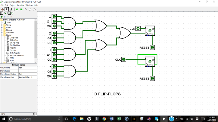
Schematic of D Flip-Flop Using Logisim Software [6]:
DESIGN #2 – SYNCHRONOUS COUNTER: J-K FLIP-FLOPS
Table 5: State Definition Table (Design 2 – J-K Flip Flops)
| State | Definition | Binary values |
| S0 | Reset/Initialize, no sequence | 00 |
| S1 | Count 1 | 01 |
| S2 | Count 2 | 10 |
| S3 | Count 3 | 11 |
Figure 4: State Transition Diagram (J-K Flip-Flops)
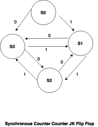
Table 6: State Transition Table (J-K Flip-Flops)
| Input | Present State | Next State | JK Inputs | |||||||
| x | State | Q1 | Q0 | State | Q1+ | Q0+ | J1 | K1 | J0 | K0 |
| 0 | S0 | 0 | 0 | S3 | 1 | 1 | 1 | X | 1 | X |
| 0 | S1 | 0 | 1 | S0 | 1 | 1 | 1 | X | X | 0 |
| 0 | S2 | 1 | 0 | S1 | 0 | 1 | X | 1 | 1 | X |
| 0 | S3 | 1 | 1 | S2 | 1 | 0 | X | 0 | X | 1 |
| 1 | S0 | 0 | 0 | S1 | 0 | 1 | 0 | X | 1 | X |
| 1 | S1 | 0 | 1 | S2 | 1 | 0 | 1 | X | X | 1 |
| 1 | S2 | 1 | 0 | S3 | 1 | 1 | X | 0 | 1 | X |
| 1 | S3 | 1 | 1 | S0 | 0 | 1 | X | 1 | X | 0 |
| Synchronous Counter – State Transition Using J-K Flip-Flops | ||||||||||
Tables 7-10: K-Maps for J-K Flip-Flop Design
| x \ Q1Q0 | 00 | 01 | 11 | 10 |
| 0 | 1 | 1 | X | X |
| 1 | 0 | 1 | X | X |
| Synchronous Counter J-K Flip Flops – (J1) K-Map | ||||
| J1 = x’ + Q0 | ||||
| x \ Q1Q0 | 00 | 01 | 11 | 10 |
| 0 | X | X | 0 | 1 |
| 1 | X | X | 1 | 0 |
| Synchronous Counter J-K Flip Flops – (K1) K-Map | ||||
| K1 = x’Q0‘ + xQ0 | ||||
| x \ Q1Q0 | 00 | 01 | 11 | 10 |
| 0 | 1 | X | X | 1 |
| 1 | 1 | X | X | 1 |
| Synchronous Counter J-K Flip Flops – (J0) K-Map | ||||
| J0 = 1 | ||||
| x \ Q1Q0 | 00 | 01 | 11 | 10 |
| 0 | X | 0 | 1 | X |
| 1 | X | 1 | 0 | X |
| Synchronous Counter J-K Flip Flops – (K0) K-Map | ||||
| K0 = x’Q1 + xQ1‘ | ||||
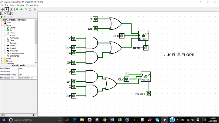
Figure 5: Schematic for J-K Flip-Flops
I hope you find these project results interesting and useful, as well as a good demonstration of how powerful these relatively simple circuits can be. If you would like more information, I recommend the text by Alan B. Marcovitz, Introduction to Logic Design. [7] You can also download the Logisim digital-logic simulation software for free, at: http://www.cburch.com/logisim/ [8].
References:
[1] V. Pedroni, Digital Electronics and Design with VHDL, Morgan Kaufmann (2008).
[2] A.M. Niknejad, Latches and Flip Flops, University of California-Berkeley (2010). Available: http://rfic.eecs.berkeley.edu/ee100/pdf/lect24.pdf
[3] J.P. Eckert, A Survey of Digital Computer Memory Systems, Proceedings of the IRE, Vol. 41: Issue 10, IEEE Explore, Available: http://ieeexplore.ieee.org/document/4051207/
[4] K. Bigelow, The S Flip-Flop (2017), Available: http://www.play-hookey.com/digital/sequential/d_nand_flip-flop.html
[5] The JK Flip Flop. Available: http://www.electronics-tutorials.ws/sequential/seq_2.html
[6] Logisim. Available: http://www.cburch.com/logisim/
[7] A. Marcovitz, Introduction to Logic Design (3rd ed.), McGraw-Hill (2010).
[8],[6], supra.
